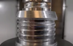
The occurrence of burring is a prevalent issue throughout the machining procedure. Burrs can manifest at various stages of CNC machining, encompassing processes such as stamping, molding, turning, milling, drilling, plasma cutting, water jet cutting, laser cutting, and several others.
When burrs form, they may take one of three main types:
- Rollover burrs: Rollover burrs are the most common. They look like tiny bits of curled metal projecting from the part.
- Poisson burrs: Poisson burrs occur when too much metal collects at the end of the part and extends sideways.
- Breakout burrs: Breakout burrs swell upwards and appear as though they are breaking out of the part.
How to access Deburring in Fusion 360
The Fusion 360 Machining Extension offers a deburring feature as part of its capabilities. Within Fusion 360, the deburring toolpath is designed to effectively combat burrs by automatically identifying external sharp edges and systematically eliminating them throughout the entire component.
This toolpath operates by indenting the surface to a degree specified by the user, effectively eradicating the burrs. It is applied to regions where corners exist between surfaces that undergo distinct directional changes. By guiding the tool along the edge, it effectively eliminates the problematic sharp burrs. Consequently, the need for manual deburring is substantially diminished.
Furthermore, the deburr toolpath is compatible with 3, 4, and 5-axis operations, serving to replace labor-intensive manual deburring tasks. This translates into notable time and cost savings, sparing you from unnecessary frustration.
Deburring in Autodesk Fusion 360
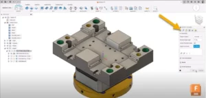
To begin, accessing the deburr function within the manufacturing workspace requires enabling the Machining Extension and navigating to the 3D drop-down menu.
Before initiating your initial deburr toolpath, it’s crucial to grasp the range of tool geometries that Fusion 360 accommodates. Supported tool types include bullnose, lollipop, chamber, spot drills, flat-end mills, and tapered tools. It’s worth noting that certain tools may necessitate additional considerations, which encompass:
- Spot drills are supported in 3, 4, and 5-axis; however, you’ll need to enable the “cut at a fixed point on the tool” option in the multi-axis tab in order to use them.
- When deburring with an endmill, the side portion of the tool is used for deburring edges. As a result, you’ll need to again, like spot drills, check “cut at fixed point on the tool” in order to use end mills for deburring your parts.
Next, you’ll need to define how the toolpath identifies edges in the geometry tab. “Automatic” interrogates the entire model’s geometry and attempts to machine all of the external edges.
(Image courtesy of Autodesk)
Specifying a “selection” will limit the toolpath to only the user-defined edges specified. There are additional options that allow you to exclude additional edges that are too close to fixturing or clamps.
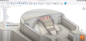
Minimum Edge Angle
Typically, a minimum edge angle is employed to automatically filter out noticeably obtuse edges during the detection process. This function parallels the concept of the bi-tangency angle in the pencil toolpath and the threshold angle found in the steep and shallow features. Any edge with an angle below the specified user-defined threshold will be disregarded.
Illustrated in the following example is an edge possessing a draft angle of 12 degrees relative to the horizontal face it connects to. To prevent the detection and subsequent deburring of this edge, the minimum edge angle should be adjusted to a value exceeding the draft angle of the edges undergoing deburring. In general, the greater the obtuseness of an edge (approaching 180 degrees), the less pronounced the burr tends to be.
(Image courtesy of Autodesk)
Passing Tab
In the passing tab, you can deburr edges in one of two ways:
- Chamfering: When using the chamfering option, the tool runs along the edge to produce a chamfered edge.
- Filleting: should be used with multiple passes and runs the tool so that the final edge appears filleted.
The edge configuration dictates the extent of material removal from the edge in the deburring phase. Under the “constant width” setting, the chamfer’s width remains consistent for every edge. Yet, the depth of the cut might differ based on the machined geometry to uphold this unchanging width.
Conversely, the “constant depth” approach ensures a uniform chamfer depth across all edges. In this scenario, the chamfer’s width can fluctuate as required by the geometry being machined, in order to sustain the designated depth.
Deburring corners between edges
The deburr toolpath is applicable for addressing the deburring of edges’ intersections as well. Certain corners necessitate deburring, but their accessibility is restricted by the geometry’s characteristics. Enabling the “cut with tip of tool” option prompts the deburr tool to enhance corner deburring by utilising a greater portion of the tool’s tip.
If you’re running an older generation controller, which can lead to jittery and stuttering machine motion, you can make the machine motion smoother by checking the “add loops for smooth motion” box. This offers smoother motion control when the tool transitions between edges by way of circular loops.
Multi-Axis Tab
Lastly, we have the multi-axis section. In certain scenarios, employing multi-axis capabilities becomes essential to grant the tool greater access for deburring a more extensive portion of the component.
Opting for the 3-axis mode limits machining to edges within the tool’s physical reach. Meanwhile, the 4-axis mode proves valuable when dealing with a rotary-style part that necessitates deburring, requiring the incorporation of an A or B-axis.
In the 4-axis configuration, the principal tilting approach can be categorised as either “to rotary axis” or “zero lead angle.” With “to rotary axis,” the tool tip consistently aligns with the specified rotary axis. Further tilting entails a corresponding tilt toward the rotary axis.
Conversely, the “zero lead angle” aligns the tool with the average angle between the two edges undergoing machining. Introducing additional tilt beyond the zero lead angle subsequently guides the tool further towards the rotary axis.
Machine Motion Smoothness
To enhance the fluidity of machine motion when employing the deburr toolpath, it is advisable to configure the high feed rate mode within the linking tab to “always use high feed.” This adjustment usually results in smoother linking movements, ensuring the synchronisation of your machine’s axes during transitions to their subsequent orientations.
I want to do all of the above…but i’m still not sure?
Looking to take the manual process of deburring out of your current workflows? Talk to our sales team about purchasing Fusion 360. If you are already a Fusion 360 user and want to unlock this powerful feature, get in touch with our customer success team.