Additive Manufacturing is a very powerful technology that can allow you to quickly make your designs a reality. However, like all manufacturing methods, there are manufacturing constraints of the technology to take into account. Just because you can design something does not necessarily mean you can make it. These constraints will depend in part on the additive technology type and the specific machine that you are using, so it is always best to check the recommendations from the printer manufacturers, but this blog outlines some of the key general points to think about when Designing for Additive Manufacturing, and how you can use Fusion 360 to design your models to account for these.
Overhangs
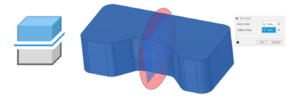
One of the main considerations for an additive build is which faces of the model will need to be supported. For most additive technologies the material will not need to be supported if it is built on top of the previous layer. This means that if building directly upwards usually you will not need supports, and this is also the case when building out at an angle, called the Overhang Angle, up to a certain value. If the overhang angle is too large, usually over 45 degrees, then the material will need to be supported.
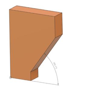
If you want to reduce the number of support structures you are using, perhaps to keep the build time or material use to a minimum, or to reduce the amount of post-processing time involved with removing these supports, it could be necessary to make sure you are not going over the critical overhang angle. When designing using Fusion 360 you can ensure this by defining any sketches that will create an angled face to be less than the critical overhang angle, or when using the Draft tool not adding any draft angles on that are larger than the overhang angle. You can also use the Draft tool to edit the model to decrease the angle of existing faces if necessary. This also works for any imported models.
Features
Some types of features will print better than others. Sharp edges or corners should be avoided as these are more susceptible to warping. Instead, fillets should be used where possible. When using Fusion 360 you can use the Fillet tool to easily replace any sharp edges with a rounded fillet.
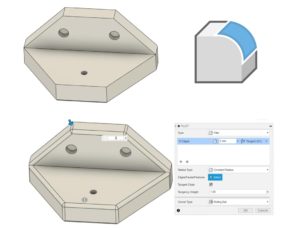
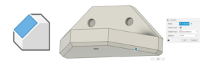
The exception to this rule is if the fillet is curving onto the build plate then instead a chamfer should be used. This is because a fillet is more prone to warping and peeling away from the build plate. You can use the Chamfer tool in Fusion 360 to easily add these in to your model instead. Where necessary it is possible to delete any fillets first, by either selecting the faces from the model or the Fillet item from the Timeline.
Whole Model Edits
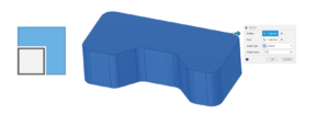
In all methods of additive manufacturing, there will be some form of warping and shrinkage due to the loss of heat from the material. For many models, they may appear to be printed undersize due to this shrinkage. If the fit of your finished part is critical, then you may need to adjust for this shrinkage. One way to do this while using Fusion 360 is to scale your model up to account for the expected shrinking. You can do this using the Scale tool.
To work out the factor to scale your model by, the best thing to do is print a test part, measure some features and make note of the actual printed size versus the nominal CAD model size. From this, you can then work out your scale factor to use for future prints while using the same print parameters. Another factor to consider is the size of your design compared to the size of your build plate. If your model is quite large you may not be able to print it in one go depending on the machine you are using. You may be better breaking the model down into smaller parts and printing these separately. If this needs to be done, Split Body can be a useful tool in Fusion 360. This will allow you to break a body down into separate parts.
This is also a useful method for splitting a model up into separate parts in order to make them easier to print than the original full model would be. These parts can then be assembled after production. For example, if trying to print a sphere this may require high support structure use.
Minimum Detail Size
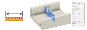
Although very fine detail on a model might be a nice addition, it may sometimes not be possible to achieve when additively manufacturing it. Depending on the additive technology type, the minimum size of detail that can be reached could be down to the nozzle size of the printer, the layer height, or for example the laser beam width. Whatever this minimum size is controlled by it will vary for each machine, so it is important to know this value for the particular machine you plan to print on.
Once you know this value it may be necessary to take it into account when designing a model or cause the need to edit a model. For example, there will be a minimum wall thickness achievable, which will be equal to this minimum detail size. During the design stage in Fusion 360, it could be important to make sure no walls are created below this size, by controlling the dimensions of any sketch items. Alternatively, a model may need to be checked for this which can be done using the Measure tool.
If it is found the wall thickness is too small, using the Press Pull tool is a very effective way of quickly editing surfaces to add (in this case) or remove material.
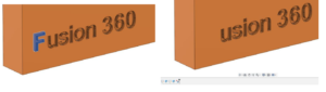
The same thing goes for other detailed features, such as text or small slots or embossed features. Again, for these the minimum detail size value should be kept in mind when designing with the sketching tools in Fusion 360. Alternatively, the Measure tool is useful again for these types of features, and the Press Pull tool may be useful to edit them if needed. It is also worth remembering that any detail will add time to the build, so it could be best to simply delete these features if they are very fine. Using Fusion 360 it is very easy to simply select faces and delete them, and the material around the faces will be automatically filled in. This deletion itself can then be removed later using the Timeline.
All of the above and more is covered in detail in our Design for Additive Manufacturing 2 day training course. Learn more about topology optimization, existing additive manufacturing technologies, and how to get the best prints from your designs. Contact the Cadspec team to find out more.


